Makin’ Mounts
When we decided to build a street gasser there were only a few things we knew for sure: The car would have a straight axle, a blown Hemi, and fenderwell headers. Granted that wasn’t much of an initial plan, but after finding our ’50 Plymouth three-window, the concept of RamRodder-a car loosely based on the Ram Chargers altered from long ago-started to come together.
As most projects go this one is lumbering along. So far we’ve added a Fatman stub to the front of the stock frame and have a Speedway straight axle mocked up. In the rear, a Currie 9-inch is attached to Morrison ladder bars. We’ve modified the firewall to accommodate our supercharged 392 and now it’s time to put it in place.
THE CHRYSLER GETS A GM TRANS
Several years ago when we first got the itch to build a gasser we collaborated with Hot Heads and Pro Machine and built a blown Chrysler Hemi. Unfortunately other projects got in the way so, other than being cranked over on a regular basis, our 392 has been sitting in the shop gathering dust. Built as a drivable, reliable street engine it made peaks of 604 hp and 580 lb-ft torque, but what’s really impressive is the 560 lb-ft torque average from 2,500 to 6,000 rpm-and that’s with 91-octane pump gas and the blower under driven with the biggest pulley available.
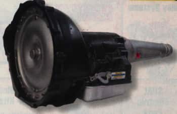
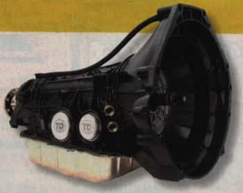
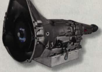
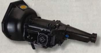
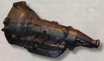
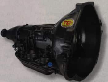
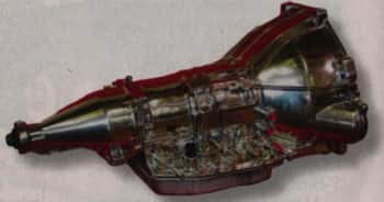
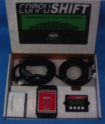
To reliably transfer the power this engine is capable of producing, we needed an equally stout transmission, so we turned to Gearstar for their recommendations. Their response was in the form of the King Kong of automatics; a Level V 4L85E. Thanks to a laundry list of improvements, including a Yank converter, Alto Redline frictions, Kevlar band, and a host of Gearstar’s own high-performance hard parts, this transmission is capable of handling drag strip launches with 1,000 hp yet, with the lock-up converter, and specially programmed computer it’s civilized on the street (we’ll get more into that when RamRodder is on the road).
To bolt the Gm transmission to the Chrysler block an adapter would be required and Pat McGuire of Wilcap handled that. One of the oldest names in the adapter business, they supplied the adapter plate, flexplate, crankshaft spacer, and the necessary hardware to bolt the engine and transmission together.
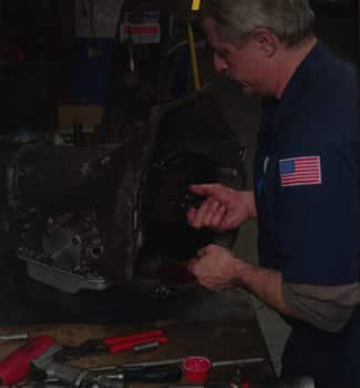
MAKING MOUNTS
As we said, fenderwell headers were planned for this project before we even had a car, they’re just part of the gasser package. The ceramic coated set we used came from Hot Heads and we basically positioned the engine based on how they fir, as luck would have it they allowed the engine to fit closely to our modified firewall, cleared the frame without having to position the engine unreasonably high, and still provide plenty of tire clearance.
With the engine supported on blocks and positioned where it needed to be, we fabricated a pair of motor mounts and a transmission crossmember. In most cases, engines are installed at an angle, with the rear lower than the front, to help align the driveshaft. As a result, intake manifolds normally have the machine at an angle to keep the float bowls level, parallel to the crankshaft, so that’s how our Hemi is oriented in the chassis.
To make the front mounts we used engine brackets from Chassis Engineering and fabricated mounts to attach to the frame, the transmission mount was made from a combination of round tubing and flat stock.
STEP BY STEP
It’s probably apparent that we’re taking a somewhat unorthodox approach to assembling our gasser by building it around a few specific design elements, however we’re sure it will pay off in the end. Now that the engine and headers are in place we can finish the suspension and install the steering, which we can tell you will be done differently than most, but then given the car we’re building and what we’ve done so far that shouldn’t come as a big surprise.
|
Three of the things we wanted in our street gasser are in place; a blown Chrysler Hemi, fenderwll headers, and a straight axle. |
 |
 |
While fabricating the engine mounts and positioning the suspension we left our Plymouth attached to our rack/frame table. We had temporarily installed the radiator support, but we removed it to make installing the engine easier. |
|
The original transmission crossmember was riveted in place as was the shifter, clutch linkage, and brake pedal brackets. |
 |
 |
A fresh blade in a reciprocating saw made removing whatever stood in the Hemi’s way quick work. |
|
Before the Wilcap transmission adapter was bolted to the block the mounting surface and guide pins were thoroughly cleaned and deburred and a tap was run through all the threaded holes. |
 |
 |
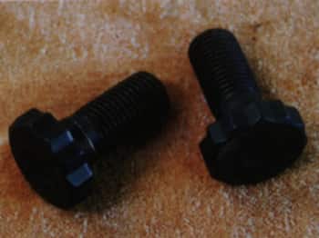
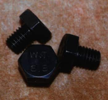
In stock form Chrysler Hemis use 7/16-inch bolts to secure the flywheel/flexplate to the crankshaft. When using an adapter, these special bolts with thin heads are necessary to clear the torque converter; they’re available from Wilcap. |
|
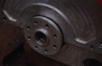
Another option is to tap the crankshaft flange for eight conventional 1/2-inch flexplate cap screws. The holes are the correct size for threading, Wilcap can supply a fixture to ensure the tap runs true. |
 |
 |
The transmission adapter slides over the stock transmission guide pins, and it’s secured with five counter sunk head cap screws from the transmission side, and one hex head cap screw from the engine side. |
|
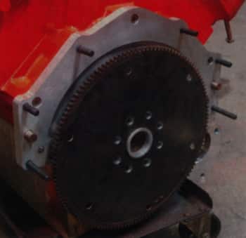
Included with the adapter is this flexplate spacer. Note the raised center register to accurately locate the flexplate. |
 |
 |
Another unique feature of these engines is that the flywheel is located by the outside diameter of the crankshaft flange. The flexplate spacer is recessed on the engine side for that purpose. |
|
A test-fit of the spacer proved that it fit tightly on the transmission flange and all the boltholes are aligned. |
 |
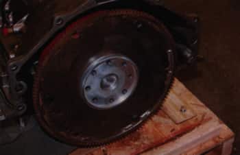 |
We checked the fit of the spacer and flexplate on the converter snout as well. Note the ring gear is offset on the flexplate toward the engine. |
|
To make sure the attaching hardware didn’t bottom out in the holes, and to make transmission installation easier, studs were used in the mounting holes. Note the ring gear is flush with the flexplate on the transmission side. |
 |
 |
The crankshaft flange was tapped for use with bolts. We ordered ARP flexplate bolts from Summit. |
|
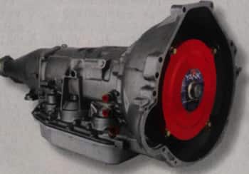
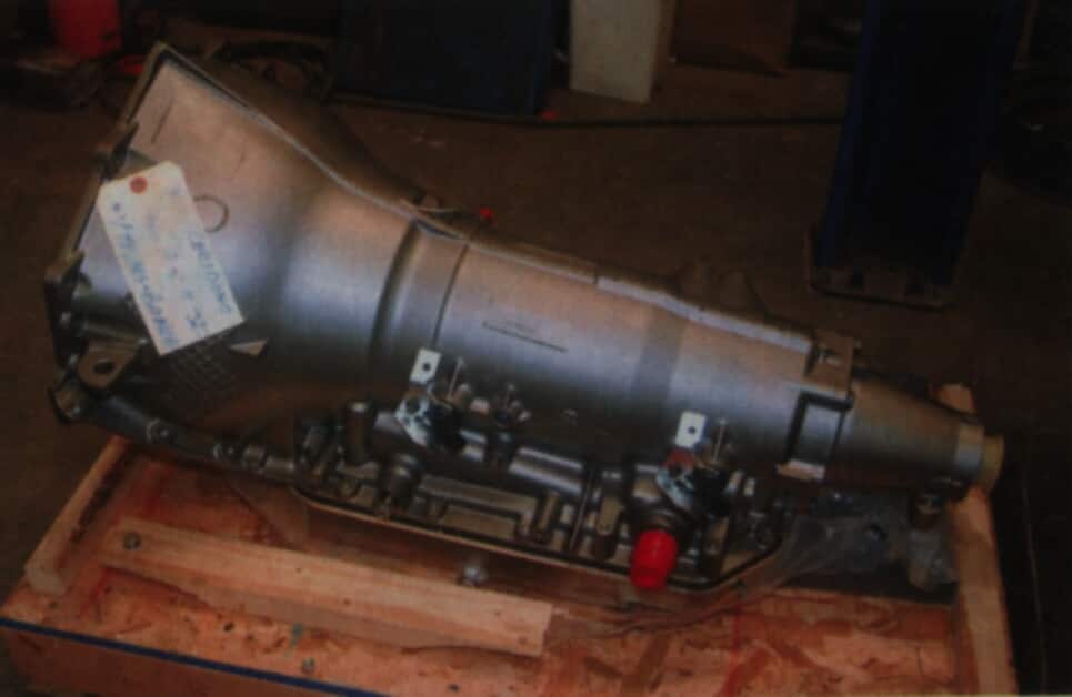
As we plan on running RamRodder down the quarter-mile we wanted a bulletproof transmission. Gearstar obliged by building a Stage V 4L85E. Along with all the other trick parts this one is equipped with a trans brake. |
 |
 |
For the ultimate in flexibility we chose a 10-inch converter for increased stall speed (for a hard launch) and lock-up for cruising the open road. |
|
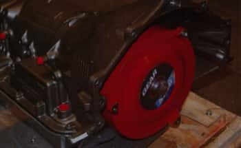
The torque converter is secured to the flexplate with three metric cap screws. Thread locking compound should be used when they’re installed. |
 |
 |
Use care when attaching the engine to the transmission, they should come together easily and fit tightly with a small amount of clearance between the flexplate and converter. Never use the fasteners to pull them together. |
|
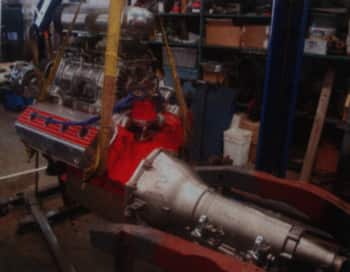
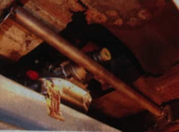
With the engine and transmission assembled they were slid into place for a test-fit. A heavy combination, this is a testament to the strength of our engine hoist and straps. |
 |
 |
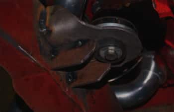
Chassis engineering brackets were bolted to the block, and they use early Ford-style rubber cushions. Templates for the frame brackets were made from cardboard. |
|
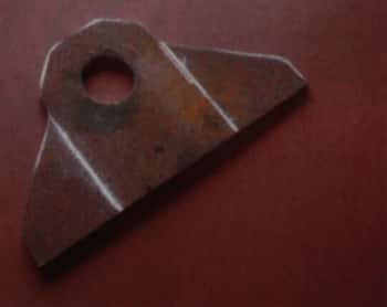
Frame brackets were cut from 1/4-inch steel plate, the large hole locates the cup that holds the upper cushion. |
 |
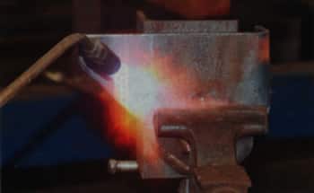 |
A large rosebud tip was used to heat the plate so the edges could be bent 90 degrees. |
|
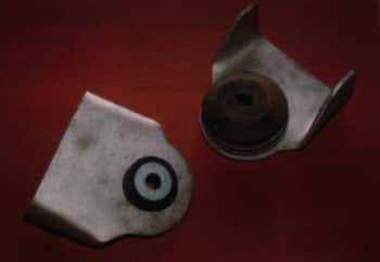
The completed frame brackets viewed from the bottom (left) and the top (right). They were made wider than necessary so they would also serve to reinforce the area where the frame and stub were joined. |
 |
 |
For additional support, two small gussets were added tot he underside of the frame brackets. |
|
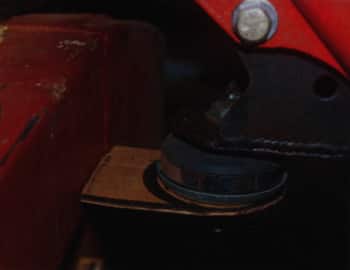
A stock GM mount was used at the rear of the transmission, a tab to attach it to the tube crossmember was made from a formed piece of flat stock. |
 |
 |
The mounting tab was notched to fit the 1 3/4-inch round tubing that would become the transmission mount. |
|
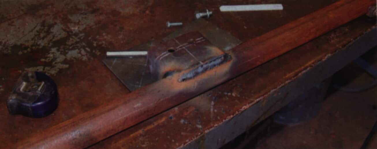
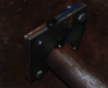
To attach the new transmission crossmemeber to the frame a pair of 4-inch square plates, 1/4-inch thick, were made to attach to the frame. Then 3/16-inch plates would be welded to the crossmemeber so it can be bolted in place. |
 |
 |
After a test-fit the 1/4-inch plates were welded to the framerails. |
|
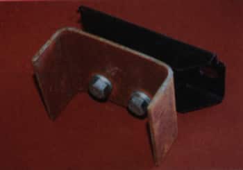
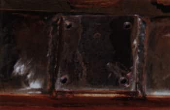
Here the 3/16-inch plates were bolted to the frame brackets, the tubing crossmember will register in the large hole. |
 |
 |
With the endplates welded to the crossmemeber it was bolted in place. Simple, but it works. |
Ready to experience top-notch transmission solutions and expert support?